Vintage Technology Repair Log

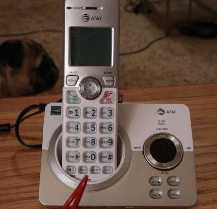
AT&T Handset Phone
Problem:
Phone was not on a surge protector. Lightening struck near the home and caused a power surge to the power outlet. The owner of the phone said they saw a spark at the phone. Afterwards it had no power.
Troubleshooting:
I assumed the fuse had blown and needed to be replaced. That's the purpose of the fuse - to take the damage of the surge and protect other components from being overloaded with power. However, I was skeptical if this were the case because it's not likely you'd see a fuses' spark outside the housing of the base.
I disassembled the base and visually saw that the fuse did not look burnt. I tested it for continuity in circuit and it was good. However, to be sure I took it out of circuit and tested it. It tested good, working condition. I then tested the power supply area, making sure the connections from the power adapter input (where the jack is inserted) were making proper connections to the PCB using diode mode on my multimeter. Everything checked out good.

This is the fuse.
Solution:
I then realized that I should have started by testing the power adapter before opening up the base of the phone. Using the voltage mode on my multimeter, with the positive (red) lead going inside the adapter and the negative (black) lead going on the outside of the adapter, I was getting a reading of 0 volts.

This shows a test for voltage in the power adapter. The multimeter gives a reading of 0 volts.
I repeated this test with a known working power adapter, and this working adapter tested a correct output of 6 volts. This confirmed that the original power adapter that tested 0 volts was no longer working.

This shows a test for voltage in the confirmed working power adapter. The multimeter gives a reading of 6 volts.
I replaced the adapter with one of equal value (in both AC and DC output) and the phone base powered on.

Problem #2:
I connect the handset to the base of the phone. Originally it connected fine, but I heard a low buzzing sound while the phone was in use. I assumed this was an antenna issue that I may have caused when desoldering the antenna to access the PCB easier. I carefully did a solder reflow where the antenna was connected, but the issue persisted. I took the batteries out of the phone, waited 15 seconds, then put the batteries back in the phone and put the phone onto the base. Now I was getting an even worse error, "Out of range or no pwr at base". "Pwr" meaning "power". After looking online it seems as if the phone has to be repaired, or registered to the base again. After following instructions on how to do so, I was able to get the phone to enter "registering" mode. However, the attempted registering fails every time.
Troubleshooting:
There is definitely still an issue with the base of the phone. Continuinty wise everything seems fine. I assume a component is not functioning as intended, but I'm not sure what component is giving me trouble. Yes, the electrolytic capacitors test fine ESR wise. I tested two transistors in circuit (One is PNP, the other is NPN) and they read faulty, but as far as I'm aware, testing transistors in circuit is likely to give a faulty reading. I still need to desolder them and test.
I think one of the problems is a shorted surface mounted ceramic capacitor (the small brick-like ones). In diode mode, I touch a lead to ground and use the other lead to touch each end of the suspect SMD capacitor. It beeps on both ends, which I think is a shorted capacitor. This capacitor is immedietly the first component after the black power wire meets the PCB, which makes sense if there were a surge, a component following the power input would go bad. Physically this capacitor is also damaged, it's cracked on the top. I'm not sure what value SMD cermaic capacitor to replace it with. There's no service manual/schematic for this device online, so I'm not sure what to get to replace this component. The size (using millimeters) is: ~2.9mm x 1mm. I can't seem to find the exact casing it would use. 1206 is closest, but the width of 1206 is too large to match my measurments (1206 measurments: 3.0mm x 1.5mm). I also can't measure the capacitor's value since it's shorted, it won't give the correct value reading. With no markings on the component, no schematics/service manual available, and no similarly sized components (this one is wider than the others), nor a donor board, I'm really not sure how to proceed with knowing the correct SMD ceramic capaicitor value to replace it with. My best guess is to look at the datasheet for the component the capacitor leads to. This capacitor leads to a "1117b 33 2n1f" semiconductor. I looked at its datasheet and am either too stupid or it's not said what recommended capacitor should lead to this semiconductor. It's most likely that I'm not skilled enough to know what to look for in the datasheet.
Conclusion for now: I am dissappointed to not have it fully functioning yet, but I did learn along the way. I'm not sure what value SMD capacitor to get to replace the faulty one with. Any input would be greatly appreciated. Once I buy that specific SMD ceramic capacitor, I will proceed with trying to replace the faulty one. Hopefully then the phone will be fully repaired. (But I see a SMD resistor with its value scraped off the top, so maybe that one is shorted too. One step at a time, though.)
Advice is appreciated only if you have knowledge/experience on this topic. Please do not offer advice if you are not knowledgable on this topic.
Phone: 725-286-3278
Email: ashleyjones@icum.to

Click here to go back to the log of repaired vintage technology.

 NEWS
NEWS
 Poems i made
 WHO AM I???


 Technology