Vintage Technology Repair Log

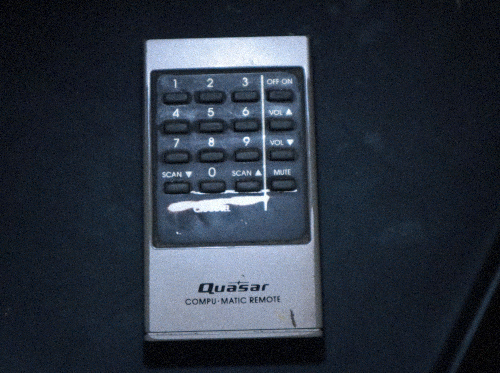
Quasar Compu-Matic Remote (1983)
Problem:
The remote would not work. Batteries that were fully functional were placed into the remote and there was zero response to touching the buttons. The remote did not work.
Troubleshooting:
I disassembled the remote. The remote is snapped together with plastic rather than using screws. I take the remote apart by using spuding tools, which are designed to get inbetween the cracks to pry apart the device at the plastic snapping points. So far I have never broken a device by doing this. One shouldn't be discouraged to open up a snapped together plastic device by using spuding tools.


This demonstrates taking a snapped together device apart by using spuding tools.
Problem #1: Wires supplying power from the batteries to the board fell off


While the remote was at first all intact, after moving the remote around some, the red and black wires which supply power from the battery compartment to the circuit broke off. I was confident that this was NOT the cause for the remote working up until when the wires snapped off. I know this because I tested for continuity using a multimeter. I placed one lead on the battery terminal, then the other lead onto the circuit where the wire soldered to. Doing this, the mulimeter beeped, which when in continuity mode, means that the two points are making a successful connection. At first both wires were making a successful connection. However, after moving the remote around a little bit, the wires snapped off as they were brittle. Now no connection was to be made since the batteries in the battery port had no means to travel the power from the batteries to the circuit, since the wires were broken off.
Solution Step 1: Removing solder where the wires were on the circuit
I had to remove the remaining wire from the circit. The first solder joints on the circuit are the ones holding in the wire. Since I need to solder in a new wire, I must remove the old solder so there will be a hole in the circuit for me to feed the new wire into. I applied flux to both solder joints, then heated one solder joint with a soldering iron. After it heated up, I removed the solder with a solder sucker. I had to do this 2 or 3 times to fully remove the solder.


However, the wire was still stuck to the board even after removing the solder. I used my iron to heat the wire and worked it out of the hole and used tweezers to pull out the wire. I repeated this with the other solder joint.

Solution Step 2: Removing the solder and old wire from the battery ports
There was still a small amount of wire left where it connects to the battery ports. I also had to remove the solder that originaly connected the wire to the battery port. This had to be done so I could solder in the new wire to the battery port. I heated up the top of the battery port (this is where the solder was) with my soldering iron until it was hot. Then I removed the solder with a solder sucker.


I had to repeat this a few times until most of the solder was gone. However, one again, the wires remained. I worked the wires out of the battery port and through the hole of the battery port, simply by warming the area with my soldering iron and moving the wire out through the hole. Then I got tweezers and pulled the wire away from the battery port.


I repeated this for the other wire/battery port.
Solution Step 3: Creating new wires
I have a box of "Dupont" wires, they have various ends on them such as male male, male female, and female female. However, since I do not need these ends, I cut off the end with wire cutters. I needed exposed wire (not wire covered with casing), so I used a wire stripper to remove the casing and expose plenty of actual wire.


I repeated this for the other side of the wire, and I also made sure this wire was similar in size to the original wires. I twisted the ends of the wire for ease. I chose to make one wire in black and one in red for consistency, but the color of the casing doesn't matter. It's all the same internally.
Solution Step 4: Soldering in the new wires to the PCB
I fed the black wire through to the hole labeled "black". The end of the exposed wire must come from the bottom of the PCB to the top where all the other solder joints are for consistency's sake.


I applied flux to the area, then using my soldering iron, heated up the PCB pad and the wire at the same time. I applied solder to solder the wire in. I trimmed the rest of the wire. I repeated this for the red wire.

Solution Step 5: Soldering in the new wires to the battery ports

This was more diffcult due to trying to get the wire into the small hole and a strange angle on the battery ports. However, I managed to feed the exposed end of the wire into the hole. On the black wire I was able to feed the wire in from the bottom of the battery port to the top of the port, since the solder will be applied at the top of the port. However, I couldn't get the red wire to feed in via the bottom, eventually having to feed it through the top. (Though later this wire broke and I was able to feed it in via the bottom.)

Once the wire was in, I applied flux to the area and applied solder. I cut the remaining wire with wire cutters. I repeated this for the back wire. (The wires uncross when I turn the PCB over.)


Now the power wires were successfully going from the battery port to the PCB, meaning the remote will now successfully carry power from the remote's battery port to the circuit.
Notes: These wires I soldered in broke at the same point the original set of wires did. I am fairly certain this is because there was too much abrupt pressure from the wire being bent to fit in the remote's casing. To solve this, I simply repeated this entire process to remove my new set of wires in favor of yet another new set, but with a thicker casing as to be more durable. Now they have no problems.
Problem #2: Suspected bad electrolytic capacitor
My first suspicion as to why this remove was not functioning was likely due to a bad electrolytic capacitor. I was originally going to replace this (quick and easy) until the wires unexpectedly broke. After fixing the wires, I tested the capacitor. The capacitor is 100uf 6.3v. It was testing at a 1.0 ESR. I couldn't find a chart giving the recommended values for this value of capacitor. However, I tested about 6 of my 100uf 6.3v Panasonic capacitors, and they all came to be a 0.7 to 0.8 ESR. This told me that the capacitor may be bad. Even if it isn't bad, it still is worth replacing.
Solution:
I heated up the solder joints for the capacitor, removed the capacitor, and put in a new capacitor of equal value, making sure that the polarity was correct when I replaced the capacitor. This was very quick to do.

After finishing this, I trimmed the leads and reassembled the remote with the batteries inside the remote. I pressed the power button by the TV and at first there was no response. I kept trying and after 2-3 tries, the TV came on. I successfully fixed the remote, the original issue was definitely an old capacitor measuing with too high of an ESR. (However, the broken wires were definitely an issue, just not the original issue).
Problem #3: Buttons must be pressed pretty hard for the TV to respond.
While I did get the remote functioning and working, the buttons had to be pressed fairly hard to get a response. About a week prior to this, I had a VCR remote stop funtioning, so I figured I knew where to start fixing this issue.
Solution:
I disassembled the remote. I took off the rubber pad buttons and cleaned the circuit where the pad meets the circuit. I assumed the remove had a case of dirty connections, cleaning them would help the remote make a better connection when a button was pressed. After cleaning the board and the rubber pad with rubbing alcohol, I reassembled.

This is from my VCR remote, but it shows what the rubber pad and inside contacts look like. These are what I cleaned with rubbing alcohol.
Notes: I'm very glad to have fixed this remote and was pleasently surprised I was able to apply a new set of wires. In times past I would have assumed the remote was fully broken and that there would be no way to fix a remote if the wires fell off. However, I'm quickly learning that most things can be fixed. The wires were more tedious than anything, not difficult, just tedious. The capacitor replacement was very easy and is another case of these old electrolytic capacitors failing due to age.
You can contact me if you are having trouble with your remote. I am not an expert and only do this as a hobby, but I may be able to provide guidance.
Phone: 725-286-3278
Email: ashleyjones@icum.to
Click here to go back to the log of repaired vintage technology.
 NEWS
NEWS
 Poems i made
 WHO AM I???


 Technology